High-impedance fault detection and isolation system

a fault detection and isolation system technology, applied in the field of electric power systems, can solve the problems of low-current faults, ineffective detection of high-impedance, low-current faults, etc., and achieve the effect of improving network safety and robust high-impedance fault isolation

Inactive Publication Date: 2014-10-14
SOUTHERN STATES
View PDF1 Cites 8 Cited by
  • Summary
  • Abstract
  • Description
  • Claims
  • Application Information

AI Technical Summary

Benefits of technology

[0011]The present invention meets the needs described above through a high-impedance fault detection system for distribution circuits using multiple independent single-phase current sensors producing asynchronous event data. Integration of information, triggered by the detection of a loss or sufficient change of current on three or four (with a neutral current) devices, is used to computationally determine the presence and direction of high-impedance faults and then report it, typically to a central control center via SCADA or another communication system, which implements fault isolation. The high-impedance fault detection system utilizes asynchronous, line-mounted single-phase current and voltage sensors with rolling data logs and a common clock or other “event trigger” to synchronize the signals to a common time scale whenever a fault event is detected. The use of asynchronous, single-phase current and voltage angle sensors with rolling data logs, along with a common clock to synchronize the signals to common time scale whenever a fault event is detected, avoids the need for simultaneous three-phase current measurement. Removing the requirement for synchronous three-phase current monitoring also allows conventional line-mounted, single-phase current sensors to be utilized. This modification produces significant savings allowing the high-impedance fault detectors to be included at more locations in the distribution network, producing more robust high-impedance fault isolation and improved network safety.

Problems solved by technology

This works well for many faults because many distribution circuit faults cause currents well in excess of the normal load current.
Although conventional FCI are effective at detecting low-impedance, high-current faults, they are not effective for detecting high-impedance, low-current faults even when they send their information to a common monitoring point.
As a result, conventional FCI technologies only detect and report high-current fault events.
In addition, there are conventional overcurrent devices with the ability to determine the location of faults on radial lines, but they only trigger for high-current faults.
As a result, virtually all of the current technologies utilized on power lines for detecting and locating low-impedance, high-current faults are ineffective for detecting high-impedance, low-current faults.
But even with three-phase synchronized information available, conventional technology is not capable of determining the location of the fault or isolating the specific line segment where the fault has occurred on power lines with multiple tap points.
Moreover, existing fault monitoring techniques located between the substations are not able to detect the presence of high-impedance faults, which limits high-impedance fault location detection to devices located in substations.
Current FCI technology used for overcurrent protection is typically not capable of providing any indication of the presence these high-impedance faults.
When high-impedance faults occur, which account for about 70% of faults, they present significant safety concerns to the public because they are often caused by energized lines touching trees or broken, still energized lines touching the ground creating significant electrical hazards.
Since high-impedance faults are not detectable by conventional overcurrent FCI sensors, their location can be nearly impossible to find.
Single-phase current monitors are not capable of determining the location of these dangerous high-impedance faults.
While some currently available techniques have been used to detect the presence of high-impedance faults by detecting a harmonic signature characteristic of a fault caused by “arcing” in the faults, these techniques do not determine the location or direction to the fault.
In addition, visual inspection also has limits because things like cracks in insulators can be difficult to find visually, for example when a crack is on the other side of the insulator from the line of sight.
The result is that a distribution circuit can experience a high-impedance fault and the utility crew may not be able to even detect the presence of the fault because the overcurrent detectors typically installed on distribution lines do not respond to the current levels created by the high-impedance fault.
Even when more sophisticated (and expensive) equipment is installed to detect the presence of high-impedance faults, the location or the direction to the fault from the monitoring equipment cannot be detected.
With currently available technology, detecting the location or the direction to the fault from the monitoring equipment presently requires even more expensive solutions.

Method used

View more

Image

Smart Image Click on the blue labels to locate them in the text.
Viewing Examples
Smart Image
  • High-impedance fault detection and isolation system
  • High-impedance fault detection and isolation system
  • High-impedance fault detection and isolation system

Examples

Experimental program
Comparison scheme
Effect test

Embodiment Construction

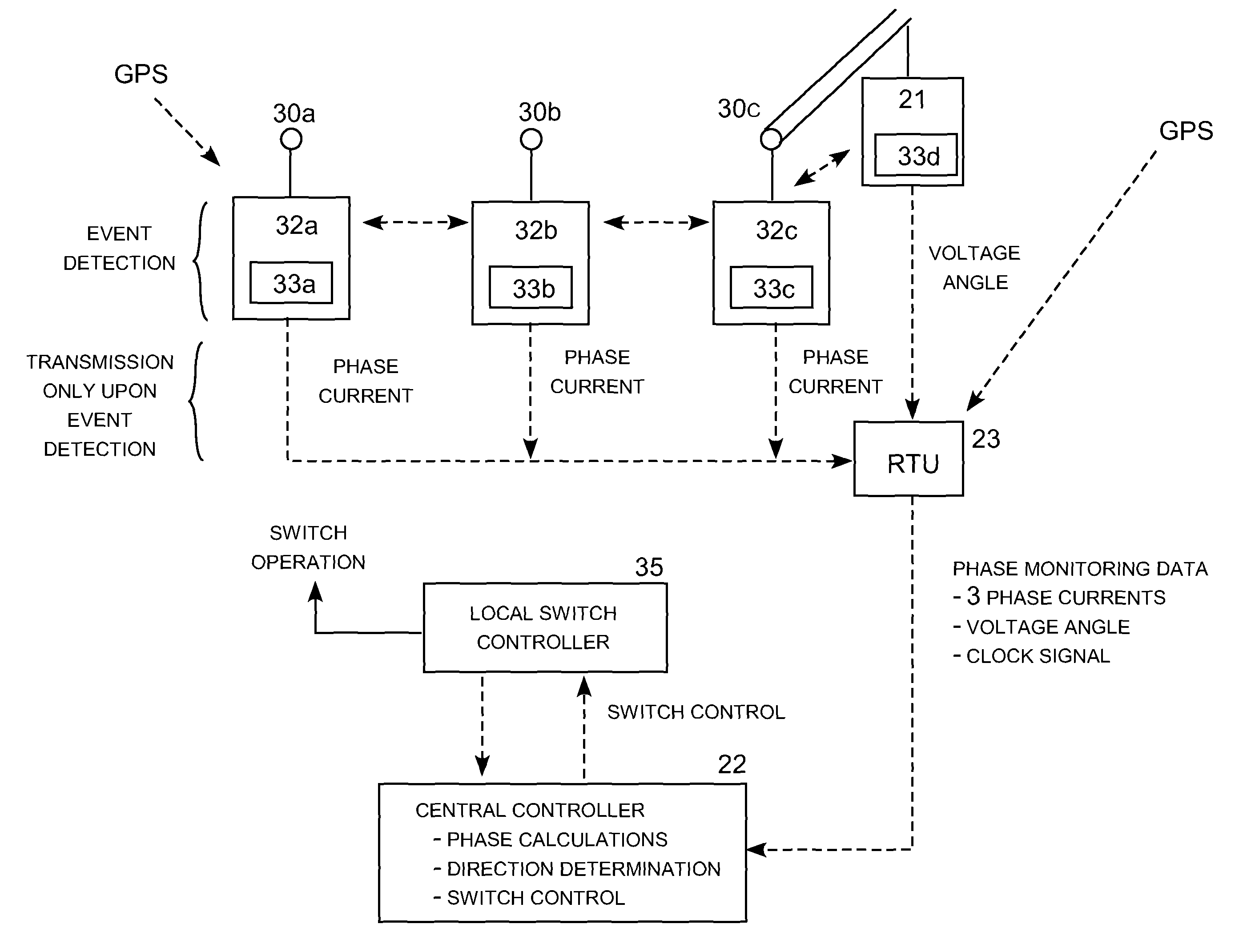
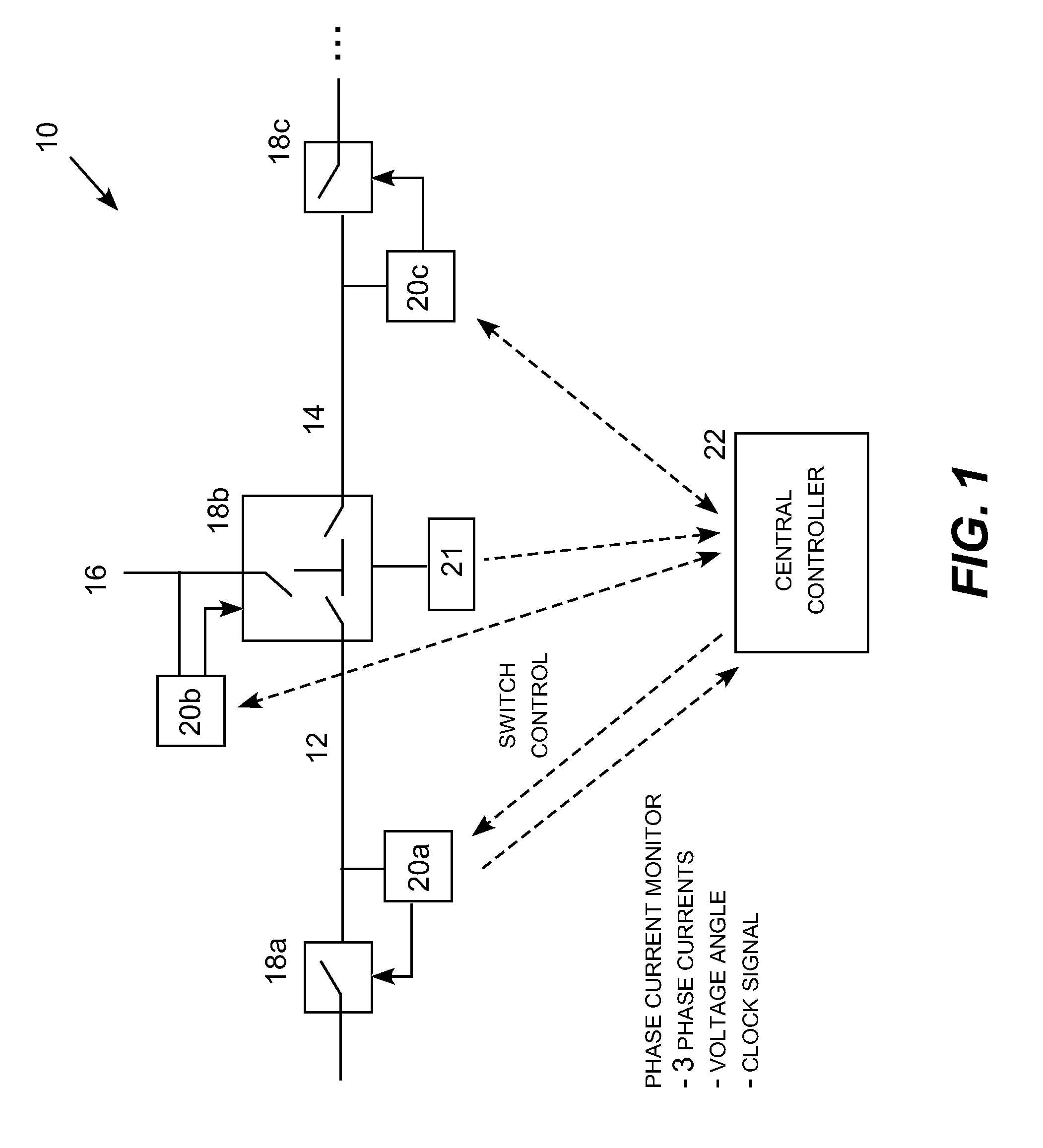
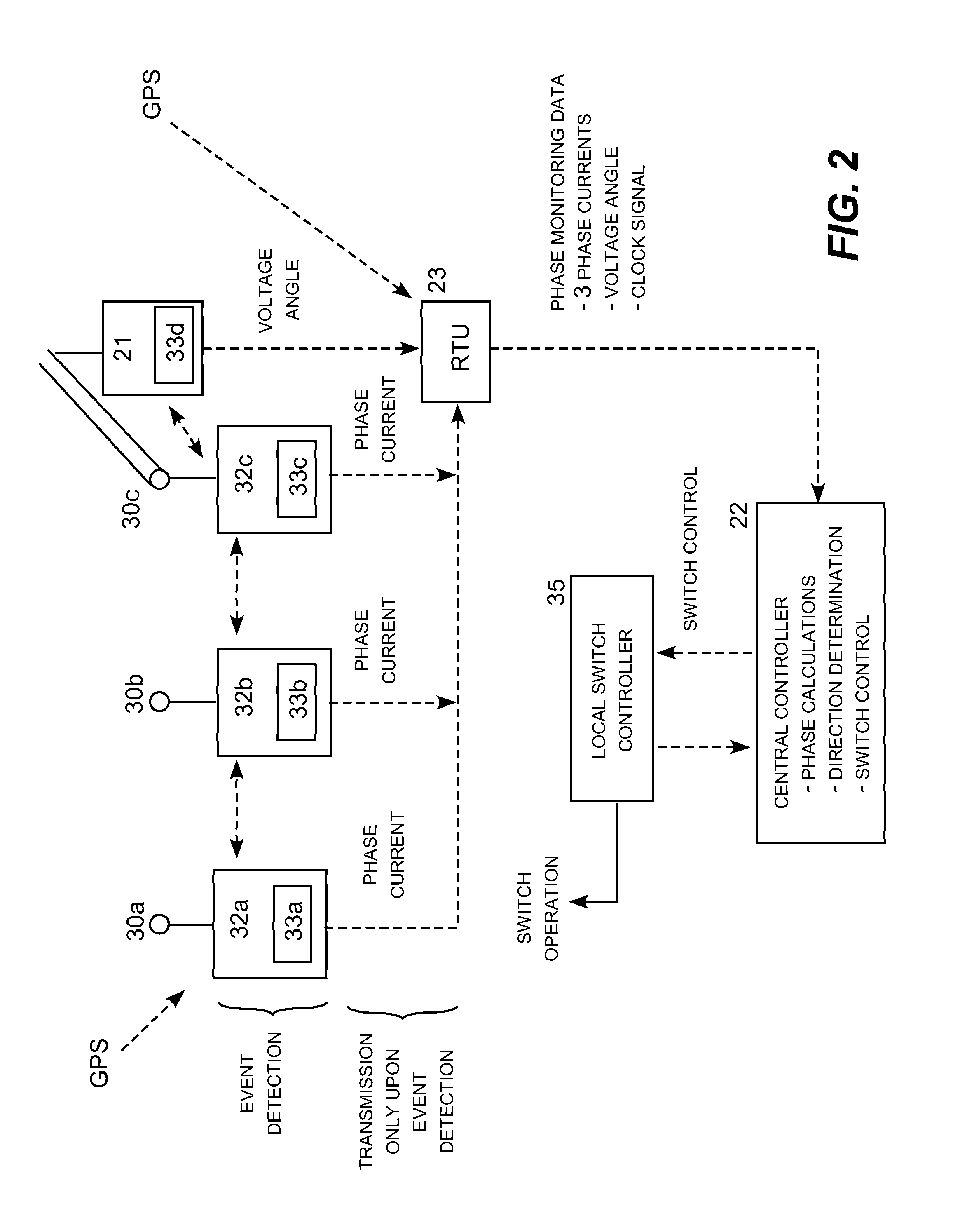
[0018]The present invention may be embodied in a high-impedance fault detection and isolation system for distribution circuits using multiple independent phase current sensors producing asynchronous event data. Specific techniques for detecting the presence of high-impedance faults using simultaneous three-phase current monitors are described in U.S. patent application Ser. No. 13 / 217,318; specific techniques for determining the direction to the fault from the sequenced currents are described in U.S. patent application Ser. No. 13 / 229,808; and specific techniques for sectionalizing the distribution network to isolate detected faults are described in U.S. patent application Ser. No. 13 / 229,095, which are incorporated by reference.

[0019]While the techniques described in these prior applications can be used to successfully detect, locate and respond to high-impedance faults, obtaining synchronized three-phase current and voltage monitoring data can be a relatively expensive solution. I...

Login to view more

PUM

No PUM Login to view more

Abstract

A high-impedance system that utilizes asynchronous, line-mounted single-phase current and voltage sensors with rolling data logs and a common clock or other event trigger to synchronize the signals to a common time scale whenever a fault event is detected. The use of asynchronous, single-phase current and voltage angle sensors with rolling data logs, along with a common clock to synchronize the signals to common time scale whenever a fault event is detected, avoids the need for simultaneous three-phase current measurement. Integration of information, triggered by the detection of a loss or sufficient change of current on three or four (with a neutral current) devices, is used to determine the presence and direction of high-impedance faults and then report it, typically to a central control center via SCADA or another communication system, which implements fault isolation.

Description

REFERENCE TO RELATED APPLICATIONS[0001]This application claims priority to U.S. patent application Ser. No. 13 / 217,318 (now U.S. Pat. No. 8,717,721); U.S. patent application Ser. No. 13 / 229,095 (now U.S. Pat. No. 8,659,862); U.S. patent application Ser. No. 13 / 229,808 (Pub. No. 2012-0062239); which claims priority to U.S. Provisional Patent Application Ser. No. 61 / 381,518; which are incorporated by reference.TECHNICAL FIELD[0002]The present invention is directed to electric power systems and, more particularly, to a high-impedance fault detection and isolation system using distributed asynchronous line-mounted phase current sensors and computational phase current sequencing of recent history event files to verify the occurrence of a high-impedance fault, identify the faulted phase, and determine the directionality of the fault.BACKGROUND[0003]Line mounted fault detectors (also known as faulted circuit indicators or FCI's) are used in distribution circuits to identify electric power ...

Claims

Login to view more

Application Information

Patent Timeline
no application Login to view more
Patent Type & Authority Patents(United States)
IPC IPC(8): H02H3/08G01R31/08H02H7/26
CPCH02H3/083G01R31/08H02H7/261
Inventor ROSTRON, JOSEPH, R.
Owner SOUTHERN STATES
Who we serve
  • R&D Engineer
  • R&D Manager
  • IP Professional
Why Eureka
  • Industry Leading Data Capabilities
  • Powerful AI technology
  • Patent DNA Extraction
Social media
Try Eureka
PatSnap group products